You can access the Concrete Results Spreadsheets by selecting the Results Menu and then selecting
For beam flexural design, the required bars are
based on the envelope moment diagrams.
Beam results are shown in the
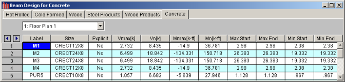
The Design Results Spreadsheet shows the controlling ultimate strengths and corresponding nominal strengths for each beam. The spreadsheet can be accessed by clicking on the Results Menu and clicking Design. The concrete results are listed on the Concrete tab. The pull down list at the top of the spreadsheet allows you to toggle between floor levels.
The Label column lists the beam label.
The Size column displays the beam size. When no adequate member could be found from the available shapes list, this field will display the text "not designed". Consider re-framing, relaxing the design or deflection requirements (see Design Optimization), or adding more shapes to the available Redesign List (see Appendix A – Redesign Lists).
The Explicit column displays "Yes" if the beam has been locked to an explicit beam size by the user and "No" when the program has selected the shape used. When you have chosen a specific shape to override the programs automatic redesign, that beam shape becomes "locked" and will not be automatically redesigned by the program.
Note
The Vmax column shows the governing maximum ultimate shear and the corresponding nominal shear strength of the beam is shown in the Vn column. Note that the nominal shear strength shown, Vn, has NOT been reduced by the strength reduction factor, Phi.
The Mmax column shows the governing maximum ultimate bending moment and the corresponding nominal moment strength of the beam is shown in the Mn column. Note that the nominal moment strength shown, Mn, has NOT been reduced by the strength reduction factor, Phi.
The Max Start & End Reaction columns display the maximum "start" and "end" reactions of the beam for ALL load combinations. If the "Show Factored End Reactions" check box in Model Settings dialog is left unchecked, these displayed forces are not factored. If the box is checked, then the displayed forces will have been multiplied by the factors in the load combinations. The sign convention assigns positive reactions to downward forces. Negative reactions, if they occur, would indicate uplift.
The Min Start & End Reaction columns display the minimum start and end reaction of the beam.
The Code Checks Spreadsheet summarizes the code check results for the beams and may be accessed by selecting Code Checks on the Results Menu. The spreadsheet has five tabs: Hot Rolled, Cold Formed, Wood, Concrete, and Wood Products. The concrete results are listed on the Concrete tab. The pull down list at the top of the spreadsheet allows you to toggle between floor levels.
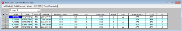
The Label column lists the beam label.
The Size column displays the beam size. When no adequate member could be found from the available shapes list, this field will display the text "not designed". Consider re-framing, relaxing the design or deflection requirements (see Design Optimization), or adding more shapes to the available Redesign List (see Appendix A – Redesign Lists).
The Explicit column displays "Yes" if the beam has been locked to an explicit beam size by the user and "No" when the program has selected the shape used. When you have chosen a specific shape to override the programs automatic redesign, that beam shape becomes "locked" and will not be automatically redesigned by the program.
Note
The Material column displays the material label from the Concrete tab of the Materials Spreadsheet that was assigned to the beam.
The Bending Check and Shear Check columns display the maximum bending check and shear check calculated by the program. These values are equal to the governing ultimate moment or shear divided by the nominal moment or shear strength. You can see the details of these values in the Bending Results or Shear Results Spreadsheets. This check is calculated at 100 stations along each beam for each load combination and the maximum check is reported. See Results Spreadsheet for more information.
The Deflection Check displays the maximum deflection check calculated by the program. This value is equal to the ratio of actual deflection to allowable deflection. You can see the details of these values in the Deflection Results Spreadsheet. This check is calculated at 100 stations along each beam and the maximum check is reported. See Beam Results - Deflection for more information.
The Loc columns display the location along the member where the maximum bending, shear, or deflection check occurs.
The LC columns display the governing load combination that produced the maximum code check.
The Cat column displays the controlling load category which resulted in the maximum deflection check.
The Shear Results Spreadsheet records the shear results for each beam and may be accessed by selecting Shear on the Results Menu. The concrete results are listed on the Concrete tab. The pull down list at the top of the spreadsheet allows you to toggle between floor levels.
![]()
The Label column lists the beam label.
The Size column displays the beam size. When no adequate member could be found from the available shapes list, this field will display the text "not designed". Consider re-framing, relaxing the design or deflection requirements (see Design Optimization), or adding more shapes to the available Redesign List (see Appendix A – Redesign Lists).
The Vn column displays the calculated nominal shear strength of the beam based on the applicable code. The Vu column displays the maximum ultimate shear force that the member experiences.
Note
The Shear Check column displays the maximum shear check calculated by the program. This value is equal to the governing ultimate shear force divided by the nominal shear strength. This check is calculated at 100 stations along each beam for each load combination and the maximum check is reported. See Results Spreadsheet for more information.
The Loc column displays the location along the member where the maximum shear check occurs.
The LC column display the governing load combination that produced the maximum code check.
The Bending Results Spreadsheet records the bending results for each beam and may be accessed by selecting Bending on the Results Menu. The concrete results are listed on the Concrete tab. The pull down list at the top of the spreadsheet allows you to toggle between floor levels.
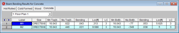
The Label column lists the beam label.
The Size column displays the beam size. When no adequate member could be found from the available shapes list, this field will display the text "not designed". Consider re-framing, relaxing the design or deflection requirements (see Design Optimization), or adding more shapes to the available Redesign List (see Appendix A – Redesign Lists).
The Mn Top and Mn Bot columns display the calculated nominal moment strength of each beam based on the applicable code. The Mu Top and Mu Bot columns display the calculated ultimate bending moment of each beam.
Note
The Bending Chk Top and Bending Chk Bot columns display the maximum bending checks calculated by the program. These values are equal to the governing ultimate moment divided by the nominal moment strength. The Bending Chk Top value represents bending that produces tension in the top fiber of the beam and the Bend Chk Bot value represents bending that produces tension in the bottom fiber of the beam. These checks are calculated at 100 stations along each beam for each load combination and the maximum checks are reported. See Results Spreadsheet for more information.
The Loc column displays the location along the member where the maximum bending checks occur.
The LC columns display the governing load combination that produced the maximum code check.
The Beam Bending Reinforcement Spreadsheet records the top and bottom flexural reinforcement steel required for the left, middle, and right locations of each beam. This spreadsheet may be accessed by
selecting Beams ![]() Concrete Reinforcing on the Results Menu and the results are listed on the Beam Bending tab.
Concrete Reinforcing on the Results Menu and the results are listed on the Beam Bending tab.
![]()
The Member column lists the beam label.
The Shape column displays the
beam size.
The Span column displays the span number corresponding to the reinforcement sections listed. Span '1' is the span beginning at the "start" of the beam and subsequent spans are numbered '2', '3', '4', and so forth moving from the "start" to the "end" of the beam.
The program assumes that the moment diagrams for all beam spans have two or fewer points of inflection. Therefore, each span is broken into Left, Middle, and Right Reinforcement Sections for flexural steel layout. Each section is further broken into Top and Bottom Reinforcement Sections. Note that a beam may have only two or even one reinforcement section. In this case, the other reinforcement sections would be left blank in this spreadsheet.
The Left Top, Left Bot, Mid Top, Mid Bot, Right Top, and Right Bot entries record the number and size of flexural reinforcement bars that are required in each of the six Reinforcement Sections. The first number indicates the number of parallel reinforcement bars in that section. The second number, preceded by the '#' sign, indicates the size of reinforcement bars used.
Note
The Beam Shear Reinforcement Spreadsheet records the shear reinforcement ties required in
each shear region of each beam. This spreadsheet may be accessed by
selecting Beams ![]() Concrete Reinforcing on the Results Menu and the results are listed on the Beam Shear tab.
Concrete Reinforcing on the Results Menu and the results are listed on the Beam Shear tab.

The Member column lists the beam label.
The Span column displays the span number corresponding to the shear regions listed. Span '1' is the span beginning at the "start" of the beam and subsequent spans are numbered '2', '3', '4', and so forth moving from the "start" to the "end" of the beam.
Each beam's shear reinforcement layout is broken into either two or four Shear Reinforcement Regions. The user can control whether the program uses '2' or '4' regions from the Concrete tab of the Model Settings Dialog. The program will try to group the required shear ties/stirrups into two or four regions and will allow for a middle region to have no shear reinforcement if the shear force is lower than that for which the code requires shear reinforcement.
The Region 1, Region 2, Region 3, and Region 4 entries record the number, size, and spacing of shear reinforcement ties/stirrups that are required in each of the Reinforcement Regions. The first number of each entry indicates the total number of ties/stirrups that are required in that region of the beam span. The second number, proceeded by the '#' sign, indicates the size of reinforcement bars used. The third number, proceeded by the "@" symbol, indicates the spacing of the ties/stirrups in that region of the beam span.
Note
Column results are shown in the three following
spreadsheets:
The Column Results Spreadsheet summarizes the code check results and records the design results for columns and may be accessed by selecting Column Results on the Results menu. The concrete results are listed on the Concrete tab.
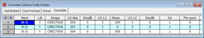
The Stack column displays the column stack label.
The Lift column displays the lift number for the physical column. Lift No. 1 is the lowermost physical column in a stack and the lifts are numbered sequentially moving up the column stack.
The Shape column displays the physical column size. When no adequate member could be found from the available shapes, this field will display the text “not designed”. Consider re-framing, relaxing the design or deflection requirements (see Design Optimization), or adding more shapes to the available Redesign List (see Appendix A – Redesign Lists).
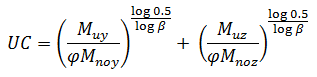
The UC Max column displays the maximum combined axial and bending check calculated by the program. This value is equal to the combined ultimate axial and ultimate bending demand divided by the actually column nominal capacity or strength. You can see the details of this value in the subsequent Axial Capacity (Pn) and Moment Capacity (Mny & Mnz) columns of this spreadsheet. This check is calculated at 100 stations along each physical column for each load combination and the maximum check is reported. See Results Spreadsheet for more information.
The Elev columns displays the absolute elevation along the column stack where the maximum axial and bending code check occurs.
The UC LC column displays the controlling load combination which produced the maximum axial and bending code check.
The Shear UC column displays the maximum shear check calculated by the program. This value is equal to the ultimate shear demand divided by the actual shear capacity or strength of the column. This check is calculated at 100 stations along each column for each load combination and the maximum check is reported. See Results Spreadsheets for more information.
The UC LC column displays the controlling load combination which produced the maximum shear code check.
The Elev columns displays the absolute elevation along the column stack where the maximum shear code check occurs.
The Dir column displays the column local axis along which the maximum shear check occurs.
The Phi Used column lists the applicable Strength Reduction Factor (f) to be applied to the nominal capacities listed in the subsequent strength columns.
The Pn column displays the calculated compressive capacity or strength of each column lift based on the applicable code. Note that this value has NOT been reduced by the strength reduction factor, Phi.
The Mny and Mnz columns display the calculated nominal moment strength of each column lift based on the applicable code. Note that this value has NOT been reduced by the strength reduction factor, Phi.
The Vny and Vnz columns display the calculated nominal shear strength of each column lift based on the applicable code. Note that this value has NOT been reduced by the strength reduction factor, Phi.
The Column Bending Reinforcement Spreadsheet shows the perimeter
flexural reinforcement steel required in each span of each column
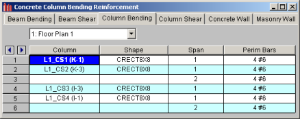
The Column field displays the column label.
The Shape column displays the physical column or lift size. When no adequate member could be found from the available shapes, this field will display the text “not designed”. Consider re-framing, relaxing the design or deflection requirements (see Design Optimization), or adding more shapes to the available Redesign List (see Appendix A – Redesign Lists).
The Span column displays the span number corresponding to the perimeter reinforcement listed. Span '1' is the span beginning at the
The Perim Bars column records the number and size of perimeter longitudinal reinforcing bars. The first number indicates the total number of longitudinal bars in that span. The second number, preceded by the '#' sign, indicates the size of the reinforcement bars used.
Note
The Column Shear Reinforcement Spreadsheet shows the shear reinforcement ties required in each shear region of each column
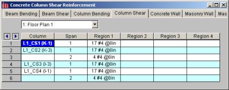
The Column field displays the column label.
The Span column displays the span number corresponding to the shear regions listed. Span '1' is the span beginning at the
Each column's shear reinforcement layout is broken into either two or four Shear Reinforcement Regions. The user can control whether the program uses '2' or '4' regions from the Concrete tab of the Model Settings dialog. The program will try to group the required shear ties into 2 or 4 regions. Unlike beams, columns cannot have a zero shear steel region. Note also that columns in tension receive NO shear capacity from the concrete.
The Region 1, Region 2, Region 3, and Region 4 entries record the number, size, and spacing of shear reinforcement ties/stirrups that are required in each of the Reinforcement Regions. The first number of each entry indicates the total number of ties/stirrups that are required in that region of the column span. The second number, proceeded by the '#' sign, indicates the size of reinforcement bars used. The third number, proceeded by the "@" symbol, indicates the spacing of the ties/stirrups in that region of the column span.
Note
The Concrete Detail Reports allow you to see the
overall force
Detail reports for concrete
Note:
 - This button will allow you to take a snapshot of the current detail report you are viewing so that it can be added to a report. View the Printing topic for more information.
 The image below is the first portion of a detail
report for a concrete beam
You can tell the Member Type by looking at the
black title in the upper left corner next to the red member label.
This title will always show the member type (Beam
The Member Information in the text above the force
diagrams shows basic member information as well as the Concrete Stress
Block type used in the solution
Each enlarged diagram will also have a slider bar at the bottom of the window for checking forces at all locations along the member. There is also an Abs Max button that will jump the slider bar to the absolute maximum value in the diagram. Note that once an enlarged diagram is opened, diagrams for other forces may be accessed via the pull down menu on the left.
The Code Check Information directly below the force diagrams is a summary of the governing checks for bending and shear, their location, and the section capacities at those locations. Separate bending checks for the most critical top and most critical bottom condition are given. Gov Muz Top and Gov Muz Bot represent the governing ultimate moment in the top and bottom of the beam respectively. Gov Vuy represents the governing ultimate shear along the local y axis of the beam.
The values phi*Mnz Top and phi*Mnz Bot represent the nominal moment strength in the top and bottom of the beam respectively, reduced by the appropriate Strength Reduction Factor, Phi, as indicated in the code. Likewise, the value phi*Vuy represents the nominal shear strength in the beam, reduced by the appropriate Phi Factor.
There is also general concrete, reinforcement,
and bar cover information about the section provided which you would need
if you were doing a hand check. Concrete Type (Normal Weight vs
Light Weight) is automatically determined from the Concrete Weight density
per the ACI code. λ is taken from the Materials spreadsheet. The E_Concrete value shown here is either the
value entered on the
The Span
Information gives the start and end of each
span centerline within the member, as well as the distance from the
The next portion of the detail report shown below contains detailed information for the placement of the Bending Steel and the Bending Span Results for each span. The bending capacity for the governing section in each span is shown as Mnz, the nominal moment strength. Rho Min and Rho Max are the minimum and maximum required reinforcement ratios at each location. These values are based on the minimum and maximum reinforcing requirements for flexural members as described in ACI 318-14 Sections 9.6.1 and 21.2.2/9.3.3.1 respectively (ACI 318-11 Sections 10.5.1 and 10.3.3/10.3.5 respectively). Rho is the ratio of reinforcement corresponding to the area of steel provided at each location, As Prvd. The As Req value is the area of steel required at each location.
Note:
The next portion of the detail report, shown above, contains detailed information for the placement of the Shear Steel and the Shear Span Results for each span. Shear results are shown by region within each span. The number of regions used is a function of the shear diagram, with the maximum number of regions being taken from the Shear Regions setting on the Concrete tab of the Model Settings Dialog. The number, size, and spacing of reinforcing bars is given for each region. Also indicated is the nominal shear strength, Vn, in each region. The portion of the nominal shear strength provided by the concrete and the steel, Vc and Vs respectively, is given for each region. The area of steel required, As Reqd, and the area of steel provided, As Prvd, are also given for each shear region and are reported as 'area of steel per unit dimension', i.e. in2/in or mm2/mm.
It should be noted that the values for Mn and Vn given in this section of the detail report are the UNREDUCED nominal capacities of the member at each span/region. The actual design capacities would be obtained by multiplying these values by their respective Phi Factors indicated in the code.
The last section of the detail report shows the Beam Reinforcement Detailing Diagrams. The Rebar Detailing portion of the report shows elevation views of the beam complete with top and bottom flexural reinforcement indicated for the left, middle, and right portions of each span. The number and size of bars required in each section is indicated on the top middle of each drawn bar. The required length of each bar is indicated on the bottom middle of each drawn bar in parenthesis. Development lengths are shown in parenthesis at one end of each bar and is represented by a dashed line. For bars at the ends of the beam, hook lengths are given in addition to the development lengths and are shown in brackets.
Note:
The values shown at the bottom corner of each span indicate the distance from the start of the beam to the face of a support. Flexural bars at the ends of the beam are measured beginning at the face of the support and bars at intermediate supports are measured to the center of the support.
The number, size, and spacing of shear reinforcement is also indicated below each span in the corresponding shear region. Each shear region is indicated by vertical lines at the bottom of the beam.
.jpg)
The Cross Section Detailing portion of the report shows cross sectional views for the start, middle, and end of each beam span. The number and size of flexural bars for each cross section are shown as well as the orientation of the shear ties/stirrups. The clear cover to each stirrup for the top and sides is shown. The overall beam dimensions for each span are indicated on the 'Start' cross section.
The image below is the first portion of a detail report for a concrete column member showing the member information, warnings, force diagrams, code checks, and span information. As can be seen, the concrete column results are very similar to the beam results with just a few additions and differences.
You can tell the Member Type by looking at the black title in the upper left corner next to the red member label. This title will always show the member type (Beam, Column, HBrace, VBrace). If the member type is "None", this title will be displayed as "Member".
The Member Information in the text above the force diagrams shows basic member information as well as the Concrete Stress Block type used in the solution, whether Cracked Sections were used for the nominal design, and the Cracked 'I' Factor that was used for that member. The Biaxial Bending Solution method that was used is also reported, and if applicable, the Parme Beta Factor.
The next section of the detail report contains the Member Force Diagrams. The diagrams shown are envelope diagrams of all solved load combinations. Any Unused Force Warnings or critical Design Warnings will be shown directly below the force diagrams in the detail report. An enlarged interactive member force diagram can be accessed by clicking on the desired diagram. For more information, see Beam Detail Reports.
The Code Check Information below the force diagrams is a summary of the governing checks for bending and shear, their location, and the section capacities at those locations. Gov Pu represents the governing ultimate axial load in the column. Gov Muy and Muz represent the governing ultimate moment about each local axis of the column. Gov Vuy and Vuz represent the governing ultimate shear along each local axis of the column.
There is also general concrete, reinforcement, and bar cover information about the section provided which are useful for hand calculation verification.Concrete Type (Normal Weight vs Light Weight) is automatically determined from the Concrete Weight density per the ACI code. The E_Concrete value shown here is either the value entered on the Concrete tab of the Materials Spreadsheet or is the calculated value based on the given f’c and weight density (if the 'E' value was left blank on the Materials Spreadsheet).
Note:
The next portions of the detail report shown above contain the Column Interaction Diagrams for the column member and the Span Information.
A Column Interaction Diagram for uniaxial bending is shown for each axis of the column. These diagrams plot the unreduced nominal strengths P vs. M for the corresponding column local axis. If the column only has bending about one axis there will be only one interaction diagram shown.
For columns under biaxial bending there is also a diagram which plots the unreduced nominal moments strengths Mz vs. My at the governing ultimate axial load, P. The last diagram is for the biaxial bending condition where the exact integration method is used and shows the interaction surface plotted at the angle of applied load (Pu, Muy, Muz). This last diagram is only shown when the Exact Integration Method is used.
The Span Information section shows the length of each span and the distances from the centerline of each support to the face of each support.
This portion of the report shown above contains the sections pertaining to the axial, bending, and shear results as well as the longitudinal and shear reinforcement.
The Column Steel section indicates the longitudinal reinforcement in each span as well as the governing load combination and location. The ultimate axial load, Pu, and the ultimate moments, Muy and Muz, are also given for each span.
The Axial Span Results show the strength reduction factor, Phi_eff, used for each span. The axial capacities for each span are shown as Pn, the nominal axial strength, and Po, the nominal axial strength with zero eccentricity. The area of longitudinal reinforcement provided in the column is listed as As Prvd and the ratio of As Prvd to the gross cross sectional area of the column is listed as Rho Gross.
The Bending Span Results show the calculated eccentricities, ecc. y and ecc. z, due to the ultimate moment about each axis divided by the ultimate axial load. The neutral axis depth for bending about the local y-axis and z-axis are listed as NA y-y and NA z-z respectively. These neutral axis locations are always given with respect to the geometric center of the column. Also shown in this section are the unreduced nominal moment capacities, Mny and Mnz, for each span of the column. If the PCA Load Contour Method is used, Mnoy and Mnoz are given, representing the maximum allowable moment for uniaxial bending at the nominal axial strength, Pn (see Biaxial Bending of Columns). If the Exact Integration Method is used, these values will be left blank.
The Shear Steel section of the report shows each span of the column broken into one or more shear regions and the number, size, and spacing of shear stirrups required in each of those regions is given. The shear design for columns is the envelope of all the shears for both directions.
The y-Dir and z-Dir Shear Span Results show the nominal shear strength, Vny and Vnz, in each shear region of the column followed by the nominal shear strengths of the concrete, Vcy and Vcz, and the nominal shear strengths of the steel, Vsy and Vsz. The area of shear reinforcement required in each shear region of the column is shown as Asy Reqd and Asz Reqd. The area of shear reinforcement provided in each shear region of the column is shown as As Prvd. Shear demand and concrete capacity are shown for both directions, but only one design of shear ties is used. Thus the As_reqd may vary for each side, but the As_prvd will always be the same.

The Slender Bending Span Results give the ultimate moments for each axis amplified for the effects of member curvature, Mcy and Mcz. These values will be left blank for spans that do not meet the criteria for slender columns in the specific direction. Also shown in this section are the values KL/r for the y and z-axis, followed by the equivalent moment correction factors Cm yy and Cm zz. The unbraced lengths of the column for each span and each direction, Lu yy and Lu zz, are given as well.
For Non-Sway frames, the assumption is that EI = 0.25*Ec*Ig. This is equivalent to setting Bdns to 0.6 in ACI 318-14 Equation 6.6.4.4.4c (ACI 318-11 Equation 10-15). For sway frame columns with a KL/r value greater than 22, the moment amplification is applied to the total moment rather than the "non-sway" portion of the moment.
Warning Log Messages will be produced when the following occurs: